For Lunatics, we need several space vehicles. For a few of them, we have existing free-licensed computer models that we can use, but others are not so easy, or need customizations. The Soyuz launch vehicle is one of these, and it was relatively easy to model, since launch vehicles are geometrically simple (basically a bunch of extruded cylinders and cones). In Part I, I'll demonstrate the basic modelling techniques I used to create the Core Stage.
Making Movies with Free Software
This article is part of an on-going series on the challenges I've faced in producing two free-licensed movies, Marya Morevna, through the Morevna Project and Lunatics, which we are working on as Anansi Spaceworks.
Although technically our Soyuz system (which I've nicknamed "Soyuz-SF") is fictional, and intended to be about 30 years in the future, the Soyuz design hasn't changed much over the last 40 years, and so this one will be based on the current "Soyuz-FG" launch vehicle.
My goal here was to create a model of the launch vehicle with each stage separately grouped so that it will be possible to animate the staging process (in a later column, I'll rig the model to make animation simpler).
This is not exactly a tutorial. These modelling tasks are challenging for me as well (part of the fun of these projects is learning how to use the tools), and my goal here is to explain how we're solving problems, without necessarily going into blow-by-blow detail. So, if you want to follow along, you should already be familiar with using Blender. For beginners, I recommend the Blender 3D Course from Tufts University.
Loading the plans
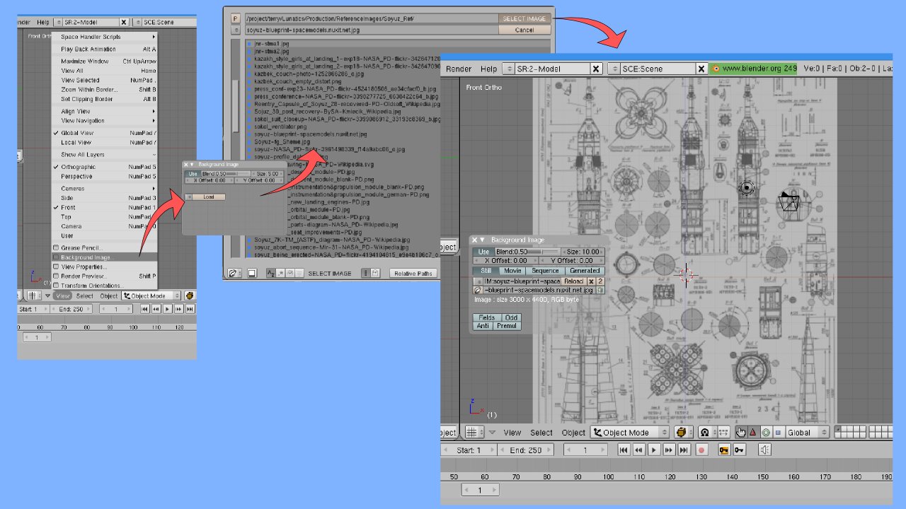
I have a set of "blueprint" drawings for the Soyuz-FG launch vehicle, which were intended to help people to make physical models, and of course, they are equally useful for making computer models. My model is based on these.
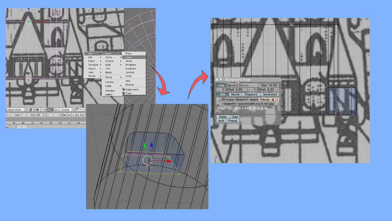
After loading Blender, in the main viewport, we'll select "View->Background Image…" and load the desired image (see Figure 1). Browse to the correct image and select it.
Note that this guide image is 2D and will only show up in the plan views as a background in orthogonal projection. This will allow us to compose our model on top of the view, matching the dimensions to the drawing.
Modeling the core stage
The basic tank shape
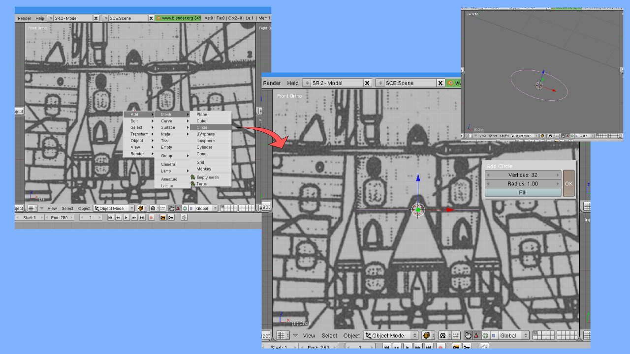
Most of the model is composed simply of interconnected cylinders, extruded successively from a circle. So, I started at the bottom of the core stage, down by the engines, and created a circle (Figure 2). You'll note that this circle is viewed edge-on, so that it looks like a line segment in this view. If you tilt your view by clicking and dragging with the middle button on the mouse, you can see that it is indeed a circle (see the inset on the right), and also that the background disappears (pressing Number Pad 1 returns to the "Front Orthogonal" view and the picture comes back).
After creating this circle, I scaled it ('S'), adjusting the size to match the base of the core stage. After this, I hit 'tab' to enter edit mode and 'E' to extrude the circle (selecting "Only Edges") and 'Z' to limit movement to the vertical axis. Figure 3 illustrates this extrusion process.
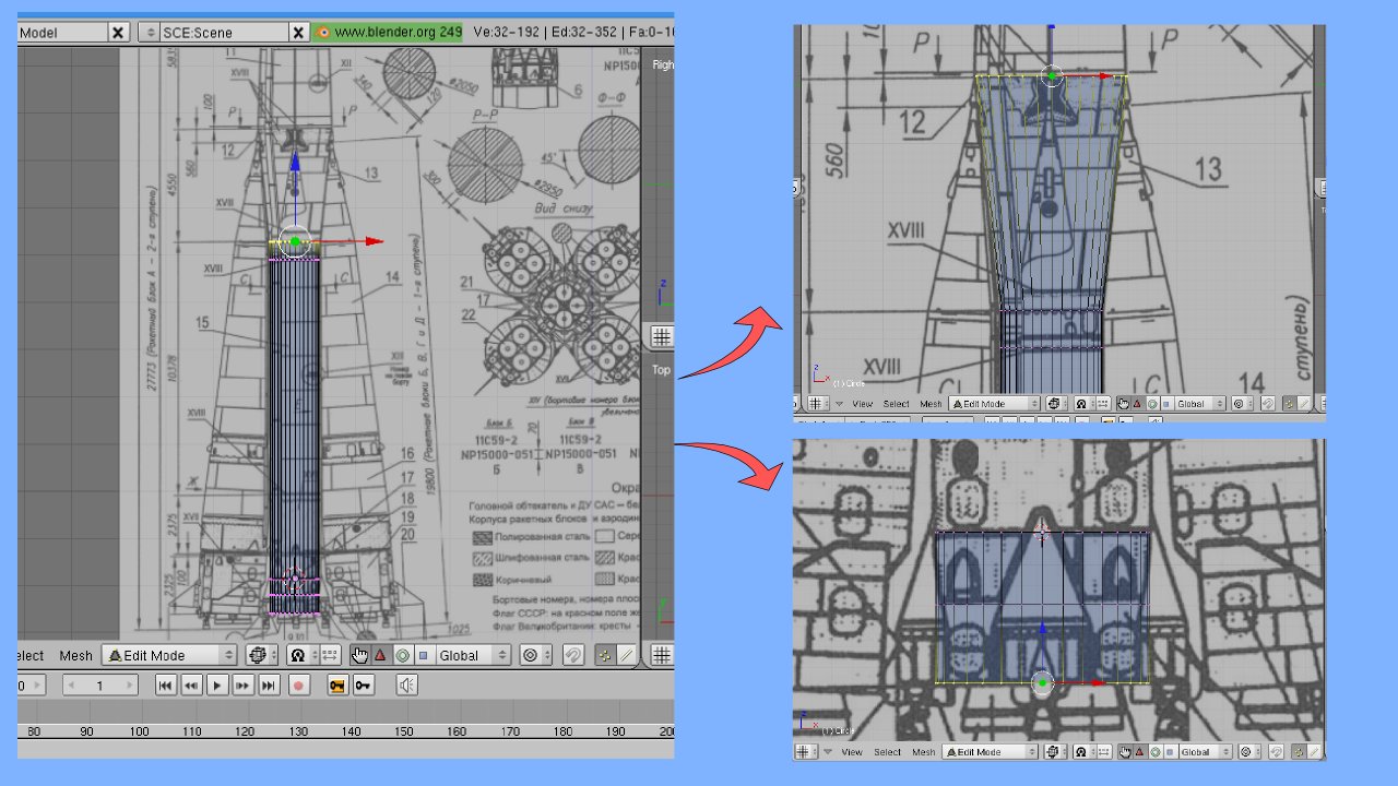
To extrude in the other direction, I re-selected the points to be extruded. To do this, I just used 'A' to toggle the "all" the point selections so that no points were selected, then 'B' to "box" select the ones I wanted (now on the opposite end of the cylinder). Note that it's important to have the model in wireframe – when it's displayed as a solid, the selection is also affected! It's easy to accidentally select only half of the cylinder, which can waste quite a bit of time if you don't discover it right away.
To follow all of the contours of the stage, which changes diameter at several points, it's necessary to use the scale operation ('S') after extruding, as is also illustrated in Figure 3.
The cap of the stage requires some further detailed extrusions. I skipped the detailing of the interstage and some other fine elements. I'll come back to those in part II.
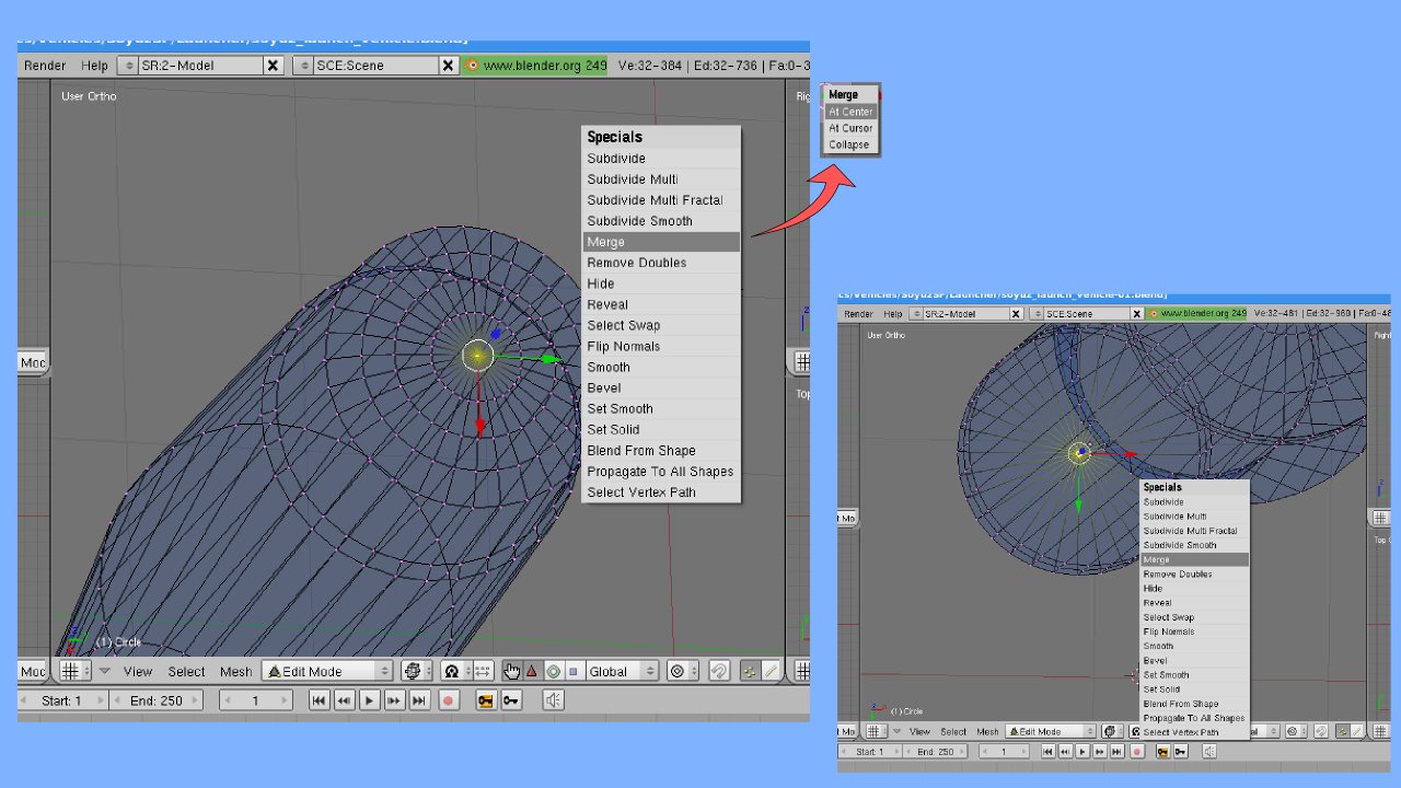
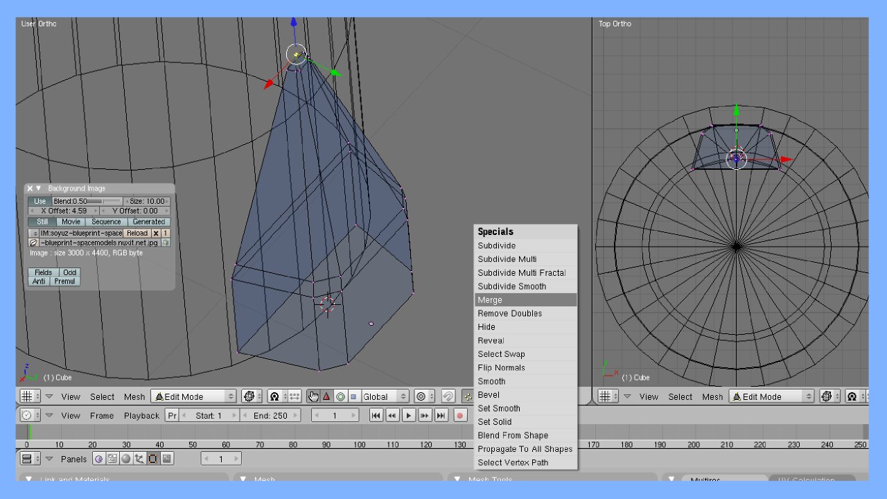
In drawing the dome, I made successive, very tiny vertical extrusions, using the scale control to reduce the diameter rapidly. Finally, I "pinched off" the extrusion by scaling it down to zero size. Of course, I then had 32 points all in the same place, which is inconvenient. So, leaving these points selected, I rotated to a better view (dragging the mouse with the middle-button pressed, to get a view like the one in Figure 4). Then I typed 'W' for the specials menu, and selected "Merge", then "At Center," to turn these 32 vertices into just one (a message appears telling me that 31 vertices have been deleted).
At this point, I left editing mode to get ready for the next step. As you can see, most of the stage is already modelled.
A close look at the bottom of the stage in photographs shows that it is essentially enclosed by a flat piece of sheet metal with the rocket bells sticking through this. There is fine detail, but for this project, it will be adequate to paint that on as a texture. So, I simply pinched off the bottom of the stage (the same as for the dome) to make a flat cylinder end (also in Figure 4).
At this point, the main body element of the core stage is complete. I created the other parts as separate Blender objects and will parent them to this main object. Pressing tab to leave edit mode, I then saved the drawing (it's a good idea to do this frequently so you have something to back up to if you screw up).
Vernier Pods
Around the base of the core stage are four tiny vernier rocket pods. These I modelled as follows:
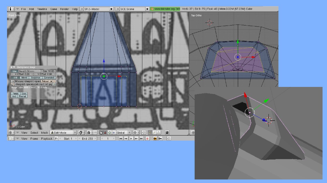
I created a cube (spacebar, 'Add…', 'Mesh', 'Cube'). I extruded an extra rectangular solid from the top. Then I scaled and moved the bottom solid to match the boxey part of the pod, then moved the top part up to the point. Scaling the points down, I pinched them off to a point, just as I did with the cap and base of the stage. The result is shown in Figure 5.
With an additional extrusion on the bottom, and a scale down, followed by another, moving back inside the cowling, I created a pocket which simulates the interior of the cowling.
Note that I had to adjust the X position of the background image to align it with the side view of the vernier pod.
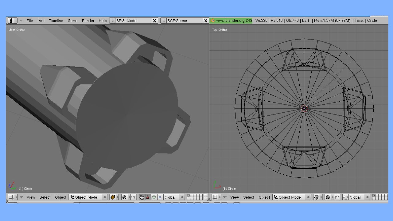
After one vernier pod was created, I used the following options to make and arrange the copies in a top view window (as in Figure 10):
- Duplicate ('Shift+D')
- Mirror with constraints ('M','X', 'M','Y')
- Object->Transform->New Center to recompute the stage center
- Object->Snap->Cursor to Selection (Shift 'S', 4) to align the cursor with the stage center
- Object->Snap->Selection to Cursor to align the pods with the center
- Move with constraints ('G', 'X', 'G', 'Y', 'G', 'Z') to match up the pods with the sides of the stage
Note that when a new center is computed for the stage, it appears near the middle of the stage's vertical height, so I had to move the pods back down to the bottom of the stage (using 'G', 'Z').
Rocket Engines
Next I created the rocket engines. These are simply cones with a ring around them, in two different sizes (main engines and vernier rockets). The modelling of the cone is basically the same as for the rocket stage. I started from the profile drawing, at the end of the bell and extruded upwards (constrained to the Z axis, as before), adjusting the diameter to fit, using the scaling ('S') operation. This takes care of the exterior.
Then I extruded the bottom, and scaled it inwards slightly (without moving up or down) to create the end. Then I extruded and adjusted diameter to model the interior of the rocket bells. These simply intersected the bottom of the rocket stage, which, though not perfectly accurate, is good enough for my needs (the only time we'll see the rockets from this angle is when they are firing). If greater accuracy is needed, it can be provided in later detailing.
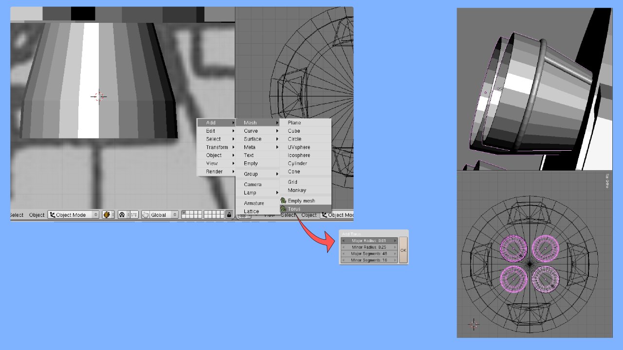
The most interesting part is the coolant loop, which I provided by putting a torus around the engine bell ("Torus" is a Python script available from the Mesh menu – it was included with Blender 2.44 and later). There are other ways I could've modelled it, but the torus made it quite simple, although it was a little tricky getting the right major and minor diameter ratios (Thinking of a torus as a solid swepted out by a circular cross-section through a circular orbit, the "major diameter" is the diameter of the orbit; the "minor diameter, that of the cross-section. If this confuses you, just experiment with different values and it will become clear). A cylinder, tilted against the side of the bell provides the coolant feed line.
Figure 9 shows the results.
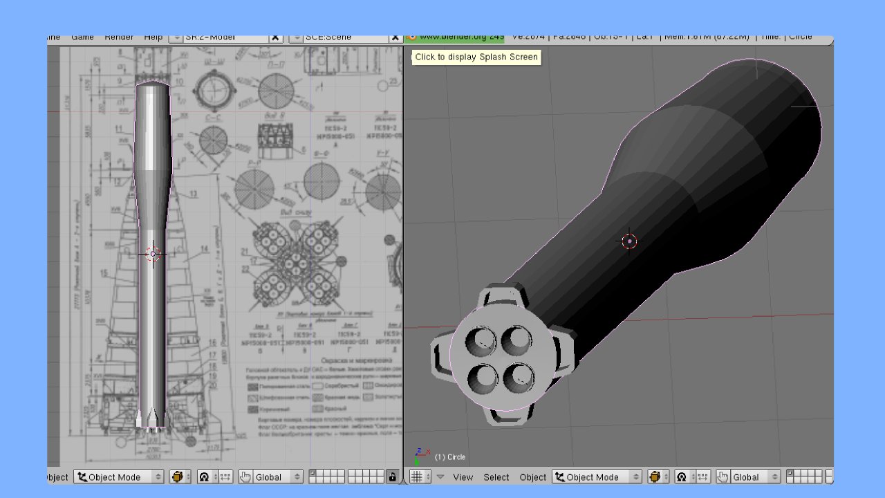
Core Stage Complete
This is the end of this part, ending with the model in Figure 10. In Part II, I'll finish out the other stages using the same techniques, but more importantly, I'll demonstrate the process of detailing the finer elements – interstage, fuel feed lines, ports, and so on. The difference between a primitive model and a really fine one is to be found in such detailing.
Licensing Notice
This work may be distributed under the terms of the Creative Commons Attribution-ShareAlike License, version 3.0, with attribution to "Terry Hancock, first published in Free Software Magazine". Illustrations and modifications to illustrations are under the same license and attribution, except as noted in their captions (all images in this article are CC By-SA 3.0 compatible).